Butt-welded aluminum flanges are also called long-necked aluminum flanges. The biggest difference between butt-welded aluminum flanges and other aluminum flanges is that they have a protruding high neck. The wall thickness of the protruding high neck will gradually butt with the height. The thickness of the pipe wall is the same as the diameter, which will increase the strength of the aluminum flange. Butt-welded aluminum flanges are mainly used in places with relatively large environmental changes, such as high-temperature, high-pressure and low-temperature pipelines.
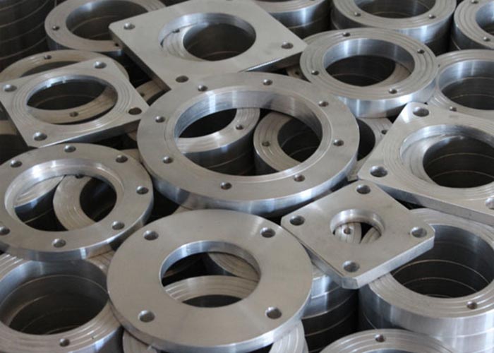
Aluminum alloy long neck flange
Aluminum alloy long neck flange
Welded high-neck convex face (W.N.R.F)Aluminium Plate Flanges-fin heat exchanger, pressure rating* is PN20
(Class150), PN50 (Class300), PN100 (Class600) three gears, the temperature range is below 200°F.
The outer dimensions of the flange are related to the pressure rating. The flange dimensions of PN20, 50, and 100 are shown in Table 1, Table 2, Table 3 and Figure 1 respectively. The thickness "C" of the flanges at all levels must be calculated and determined according to the allowable stress of the material under the working conditions of the flange. The calculation regulations are carried out in accordance with Appendix 2 of Volume VⅢ-1 of ASME Code.
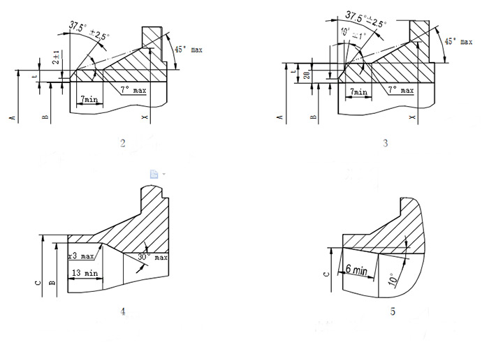
1.1 The size of the welded end of the pipe is determined by Figure 2, Figure 3, Figure 4, Figure 5 and Table 4 according to the different pipe sizes used. The material of the pipe can be the same as the flange or a different material from the flange.
2 Welding groove
2.1 When the inner diameter of the flange and the pipe are the same, when the wall thickness is t=5~22mm, beveled according to Figure 2; when t>22mm, beveled according to Figure 3.
2.2 When welding needs to use the bottom backing plate, the backing plate should be placed inside the pipe, and its bevel type shall be carried out according to Figure 4. When the inner diameter of the backing plate is the same as the inner diameter of the pipe, the thickness of the backing plate is:
δ=1/2(C-B)=1/2(A-0.79-1.75t-0.25-A+2t)=0.125t-0.25mm
Among them: B=A-2t; A——pipe outer diameter mm C=A-1.75t-1.04mm;
*The pressure rating is based on the material used in the applicable temperature range, without impact load, the maximum allowable working pressure bar (gauge pressure) PN20 is 20bar.
2.3 Material code: ASME SB247-6061-T6.
2.4 Pressure rating: PN×××.
2.5 Nominal diameter: DN×××.
2.6 Number of material book.
Flange type drawing
Example: The pressure rating is PN100, the nominal diameter is DN300mm, and the material book number is 94-081. The flange identification made by Hangyang meets the ASME SB247 standard and the material number is 6061-T6:
HYFM. ASME SB247-6061-T6, PN100, DN300, 94-081
Figure 1 Welded high-neck raised plane flange size
Table 1 PN20 (Class150) flange dimensions Dimensions unit: mm
|
Nominal nozzle size |
Flange OD |
Pot OD X |
Neck OD A |
Neck ID B |
Total flange heightY |
Center diameter of screw holeG |
Convex outer diameterR |
Screw hole diameterD |
Number of bolts N |
neck
thick t |
Convex height f |
Transition filletr |
Flange thickness C min* |
|
15 |
90 |
30 |
21.5 |
16 |
48 |
60.5 |
35 |
16 |
4 |
2.75 |
2 |
3 |
11.5 |
|
20 |
100 |
38 |
26.5 |
21 |
52 |
70 |
43 |
16 |
4 |
2.75 |
2 |
3 |
13 |
|
25 |
110 |
49 |
33.5 |
26.5 |
56 |
79.5 |
51 |
16 |
4 |
3.5 |
2 |
3 |
14.5 |
|
32 |
120 |
59 |
42 |
35 |
57 |
89 |
64 |
16 |
4 |
3.5 |
2 |
3 |
16 |
|
40 |
130 |
65 |
48.5 |
41 |
62 |
98.5 |
73 |
16 |
4 |
3.75 |
2 |
3 |
17.5 |
|
50 |
150 |
78 |
60.5 |
52.5 |
64 |
120.5 |
92 |
20 |
4 |
4.0 |
2 |
3 |
19.5 |
|
65 |
180 |
90 |
73 |
62.5 |
70 |
139.5 |
105 |
20 |
4 |
5.25 |
2 |
3 |
22.5 |
|
80 |
190 |
108 |
89 |
78 |
70 |
152.5 |
127 |
20 |
4 |
5.5 |
2 |
3 |
24 |
|
100 |
230 |
135 |
114.5 |
102.5 |
76 |
190.5 |
157 |
20 |
8 |
6.0 |
2 |
3 |
24 |
|
125 |
255 |
164 |
141.5 |
128 |
89 |
216 |
186 |
22 |
8 |
6.75 |
2 |
3 |
24 |
|
150 |
280 |
192 |
168.5 |
154 |
89 |
241.5 |
216 |
22 |
8 |
7.25 |
2 |
3 |
25.5 |
|
200 |
345 |
246 |
219 |
202.5 |
102 |
298.5 |
270 |
22 |
8 |
8.25 |
2 |
3 |
29 |
|
250 |
405 |
305 |
273 |
254.5 |
102 |
362 |
324 |
26 |
12 |
9.25 |
2 |
3 |
30.5 |
|
300 |
485 |
365 |
324 |
305 |
114 |
432 |
381 |
26 |
12 |
9.5 |
2 |
3 |
32 |
|
350 |
535 |
400 |
355.5 |
|
127 |
476 |
413 |
30 |
12 |
|
2 |
3 |
35 |
|
400 |
600 |
457 |
406.5 |
127 |
540 |
470 |
30 |
16 |
2 |
3 |
37 |
||
|
450 |
635 |
505 |
457 |
140 |
578 |
533 |
33 |
16 |
2 |
5 |
40 |
||
|
500 |
700 |
559 |
508 |
145 |
635 |
584 |
33 |
20 |
2 |
5 |
43 |
||
|
600 |
815 |
664 |
609.5 |
152 |
749.5 |
692 |
36 |
20 |
2 |
5 |
48
|
|
Nominal nozzle size |
Flange OD |
Pot OD X |
Neck OD A |
Neck ID B |
Total flange heightY |
Center diameter of screw holeG |
Convex outer diameterR |
Screw hole diameterD |
Number of bolts N |
neck
thick t |
Convex height f |
Transition filletr |
Flange thickness C min* |
|
15 |
95 |
38 |
21.5 |
16 |
52 |
66.5 |
35 |
16 |
4 |
2.75 |
2 |
3 |
14.5 |
|
20 |
120 |
48 |
26.5 |
21 |
57 |
82.5 |
43 |
20 |
4 |
2.75 |
2 |
3 |
16 |
|
25 |
125 |
54 |
33.5 |
26.5 |
62 |
89 |
51 |
20 |
4 |
3.5 |
2 |
3 |
17.5 |
|
32 |
135 |
64 |
42 |
35 |
65 |
98.5 |
64 |
20 |
4 |
3.5 |
2 |
3 |
19.5 |
|
40 |
155 |
70 |
48.5 |
41 |
68 |
114.5 |
73 |
22 |
4 |
3.75 |
2 |
3 |
21 |
|
50 |
165 |
84 |
60.5 |
52.5 |
70 |
127 |
92 |
22 |
8 |
4.0 |
2 |
3 |
22.5 |
|
65 |
190 |
100 |
73 |
62.5 |
76 |
149.5 |
105 |
22 |
8 |
5.25 |
2 |
3 |
25.5 |
|
80 |
210 |
117 |
89 |
78 |
79 |
168 |
127 |
22 |
8 |
5.5 |
2 |
3 |
29 |
|
100 |
255 |
146 |
114.5 |
102.5 |
86 |
200 |
157 |
22 |
8 |
6.0 |
2 |
3 |
32 |
|
125 |
280 |
178 |
141.5 |
128 |
98 |
235 |
186 |
22 |
8 |
6.75 |
2 |
3 |
35 |
|
150 |
320 |
206 |
168.5 |
154 |
98 |
270 |
216 |
22 |
12 |
7.25 |
2 |
3 |
37 |
|
200 |
380 |
260 |
219 |
202.5 |
111 |
330 |
270 |
26 |
12 |
8.25 |
2 |
3 |
41.5 |
|
250 |
445 |
321 |
273 |
254.5 |
117 |
387.5 |
324 |
30 |
16 |
9.25 |
2 |
3 |
48 |
|
300 |
520 |
375 |
324 |
305 |
130 |
451 |
381 |
33 |
16 |
9.5 |
2 |
3 |
51 |
|
350 |
585 |
426 |
355.5 |
|
143 |
514.5 |
413 |
33 |
20 |
|
2 |
3 |
54 |
|
400 |
650 |
483 |
406.5 |
146 |
571.5 |
470 |
36 |
20 |
2 |
3 |
57.5 |
||
|
450 |
710 |
533 |
457 |
159 |
629 |
533 |
36 |
24 |
2 |
5 |
60.5 |
||
|
500 |
775 |
587 |
508 |
162 |
686 |
584 |
36 |
24 |
2 |
5 |
63.5 |
||
|
600 |
915 |
702 |
609.5 |
168 |
813 |
692 |
42 |
24 |
2 |
5 |
70
|
|
Nominal nozzle size |
Flange OD |
Pot OD X |
Neck OD A |
Neck ID B |
Total flange heightY |
Center diameter of screw holeG |
Convex outer diameterR |
Screw hole diameterD |
Number of boltsN |
neck
thick t |
Convex height f |
Transition filletr |
Flange thickness C min* |
|
15 |
95 |
38 |
21.5 |
|
52 |
66.5 |
35 |
16 |
4 |
|
7 |
3 |
14.5 |
|
20 |
120 |
48 |
26.5 |
57 |
82.5 |
43 |
20 |
4 |
7 |
3 |
16 |
||
|
25 |
125 |
54 |
33.5 |
62 |
89 |
51 |
20 |
4 |
7 |
3 |
17.5 |
||
|
32 |
135 |
64 |
42 |
67 |
98.5 |
64 |
20 |
4 |
7 |
3 |
21 |
||
|
40 |
155 |
70 |
48.5 |
70 |
114.5 |
73 |
22 |
4 |
7 |
3 |
22.5 |
||
|
50 |
165 |
84 |
60.5 |
73 |
127 |
92 |
22 |
8 |
7 |
3 |
25.5 |
||
|
65 |
190 |
100 |
73 |
79 |
149 |
105 |
22 |
8 |
7 |
3 |
29 |
||
|
80 |
210 |
117 |
89 |
83 |
168.5 |
127 |
22 |
8 |
7 |
3 |
32 |
||
|
100 |
275 |
152 |
114.5 |
102 |
216 |
157 |
26 |
8 |
7 |
3 |
38.5 |
||
|
125 |
330 |
189 |
141.5 |
114 |
267 |
186 |
30 |
8 |
7 |
3 |
44.5 |
||
|
150 |
356 |
222 |
168.5 |
117 |
292 |
216 |
30 |
12 |
7 |
3 |
48 |
||
|
200 |
420 |
273 |
219 |
133 |
349 |
270 |
33 |
12 |
7 |
3 |
55.5 |
||
|
250 |
510 |
343 |
273 |
152 |
432 |
324 |
36 |
16 |
7 |
5 |
63.5 |
||
|
300 |
560 |
400 |
324 |
156 |
489 |
381 |
36 |
20 |
7 |
5 |
66.5 |
||
|
350 |
605 |
432 |
355.5 |
165 |
527 |
413 |
39 |
20 |
7 |
5 |
70 |
||
|
400 |
685 |
495 |
406.5 |
178 |
603 |
470 |
42 |
20 |
7 |
5 |
76.5 |
||
|
450 |
745 |
546 |
457 |
184 |
654 |
533 |
45 |
20 |
7 |
5 |
83 |
||
|
500 |
815 |
610 |
508 |
190 |
724 |
584 |
45 |
24 |
7 |
5 |
89 |
||
|
600 |
940 |
718 |
609.5 |
203 |
838 |
692 |
52 |
24 |
7 |
5 |
102 |