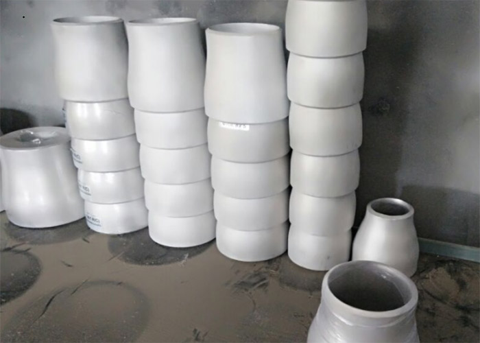
The reducer, is one of the chemical pipe fittings, used for the connection of two different pipe diameters. It is divided into Aluminum-Alloy Concentric Reducer and Aluminum-Alloy Eccentric Reducer. The reducer material includes aluminum alloy reducer 6061,1060 Aluminum Concentric Reducer, 5083 Aluminum Eccentric Reducer material and so on.

Aluminum alloy reducer
Performance and standard of aluminum reducer
The aluminum reducer in Aluminum-Alloy Welding pipe Fittings has low density, high strength, good corrosion resistance, excellent reflectivity, good plasticity, easy processing and forming, and has excellent electrical conductivity, thermal conductivity, good corrosion resistance, and high Strength and good plasticity, easy to process and cast various parts. Aluminum aluminum reducer will not produce corrosion, pitting, rust or wear. Aluminum aluminum reducer is one of the materials with higher strength among the metal materials used in construction.
The reduction forming technology of aluminum reducer is to place the flat tube blank of the aluminum reducer with the larger diameter end in the forming mold, and bind it through the target along the axis of the tube, so that the metal is along the The mold cavity is moved and shortened and formed. According to the aluminum reducer, the aluminum reducer can be divided into one-time binding molding or the method of multiple binding molding. The method of expanding diameter is to select a tube blank smaller than the diameter of the large end of the aluminum reducer, and use an outer die to expand the tube along the inner diameter of the tube.
Because aluminum reducer has good corrosion resistance, it can maintain the integrity of the engineering design for a longer period of time. Aluminum-containing aluminum reducer also combines mechanical strength and high extensibility, which is easy to process and manufacture. , Can meet the needs of architects and structural designers.
What is the difference between the size head and the reducer
This standard applies to pipe connections with a nominal pressure of PN≤1.0Mpa.
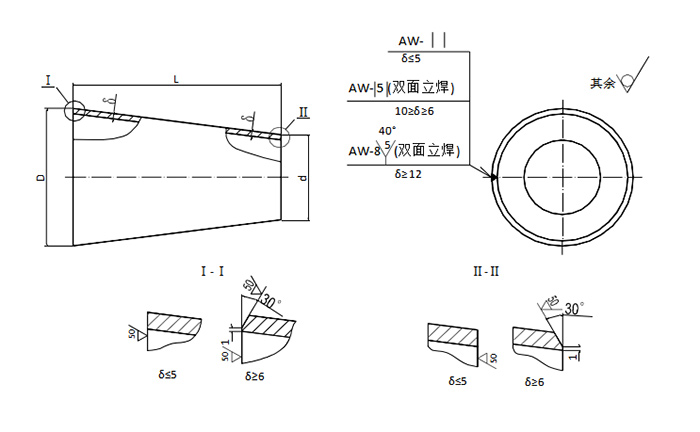
1 The type and size of the shrink connection are specified in the following figure and table:

Markup example:
Nominal diameter DN The big head is 200, the small head is 100, the outer diameter of the port is D=208, d=110, the wall thickness δ=4, the material is LF2
The contraction:
Shrink 200/100 HT5071-83
4Material: LF2 for DN large head ≤500.
DN big head ≥600 is LF4, LF2 (only for PN≤0.8Mpa)
Other requirements must meet the requirements of HT0008-83。
|
Nominal diameterDN |
Outer diameter of port |
Wall thicknessδ |
lengthL |
weight(Kg) |
Nominal diameterDN |
Outer diameter of port |
Wall thicknesδ |
lengthL |
weight(Kg) |
||||
|
Big head |
Small head |
D |
d |
Big head |
Small head |
D |
d |
||||||
|
40 |
15 |
45 |
19 |
2.5 |
65 |
0.040 |
300 |
150 |
312 |
162 |
6 |
205 |
2.38 |
|
20 |
25 |
0.045 |
200 |
212 |
2.84 |
||||||||
|
25 |
30 |
0.048 |
250 |
262 |
2.89 |
||||||||
|
50 |
20 |
55 |
25 |
2.5 |
75 |
0.059 |
350 |
200 |
362 |
212 |
6 |
300 |
4.24 |
|
25 |
30 |
0.064 |
250 |
262 |
200 |
3.08 |
|||||||
|
40 |
45 |
0.075 |
300 |
312 |
3.83 |
||||||||
|
65 |
25 |
70 |
31 |
3 |
80 |
0.097 |
400 |
200 |
412 |
212 |
6 |
400 |
6.16 |
|
40 |
46 |
0.111 |
250 |
262 |
315 |
6.24 |
|||||||
|
50 |
56 |
0.121 |
300 |
312 |
230 |
4.12 |
|||||||
|
80 |
40 |
90 |
48 |
4 |
90 |
0.196 |
350 |
362 |
200 |
3.83 |
|||
|
50 |
58 |
0.211 |
500 |
250 |
516 |
266 |
8 |
500 |
12.8 |
||||
|
65 |
72 |
0.233 |
300 |
316 |
420 |
11.5 |
|||||||
|
100 |
50 |
110 |
58 |
4 |
100 |
0.268 |
350 |
366 |
320 |
9.29 |
|||
|
65 |
72 |
0.292 |
400 |
416 |
230 |
7.07 |
|||||||
|
80 |
90 |
0.322 |
600 |
300 |
630 |
316 |
8 |
600 |
19.2 |
||||
|
125 |
65 |
133 |
73 |
4 |
120 |
0.394 |
350 |
366 |
560 |
18.7 |
|||
|
80 |
90 |
0.450 |
400 |
416 |
420 |
15.4 |
|||||||
|
100 |
110 |
0.470 |
500 |
516 |
230 |
8.72 |
|||||||
|
150 |
65 |
158 |
72 |
4 |
140 |
0.521 |
700 |
400 |
720 |
416 |
8 |
600 |
22.5 |
|
80 |
90 |
0.564 |
500 |
516 |
420 |
17.2 |
|||||||
|
100 |
110 |
0.611 |
600 |
630 |
230 |
10.3 |
|||||||
|
125 |
133 |
0.660 |
800 |
500 |
820 |
520 |
10 |
600 |
33.2 |
||||
|
200 |
80 |
208 |
90 |
4 |
150 |
0.729 |
600 |
634 |
420 |
25.2 |
|||
|
100 |
110 |
0.780 |
700 |
724 |
230 |
14.7 |
|||||||
|
125 |
133 |
0.832 |
900 |
600 |
920 |
634 |
10 |
620 |
39.8 |
||||
|
150 |
158 |
0.901 |
700 |
724 |
420 |
28.5 |
|||||||
|
250 |
100 |
260 |
112 |
5 |
180 |
1.36 |
800 |
820 |
230 |
16.6 |
|||
|
125 |
135 |
1.48 |
1000 |
700 |
1020 |
728 |
12 |
630 |
54.5 |
||||
|
150 |
160 |
1.55 |
800 |
824 |
420 |
38.4 |
|||||||
|
200 |
210 |
1.74 |
900 |
924 |
230 |
22.1 |
|||||||
2) Executive standard: GB/T 12459, ASME B16.9, JIS B 2312
3) Outer diameter range: φ21-φ610mm (1/2”-24”)
4) Pressure range: WT 2-,20mm (SCH20-SCH80)
Product material: ASME B361-1060, 5083, 6061; 6063; 6082
Applications
Features:
Corrosion resistant
Durable functioning
Malleable
Heat resistance
High strength
Excellent conductivity
Impeccable finish
Enhanced service life
Precisely designed